 Merrion Design Review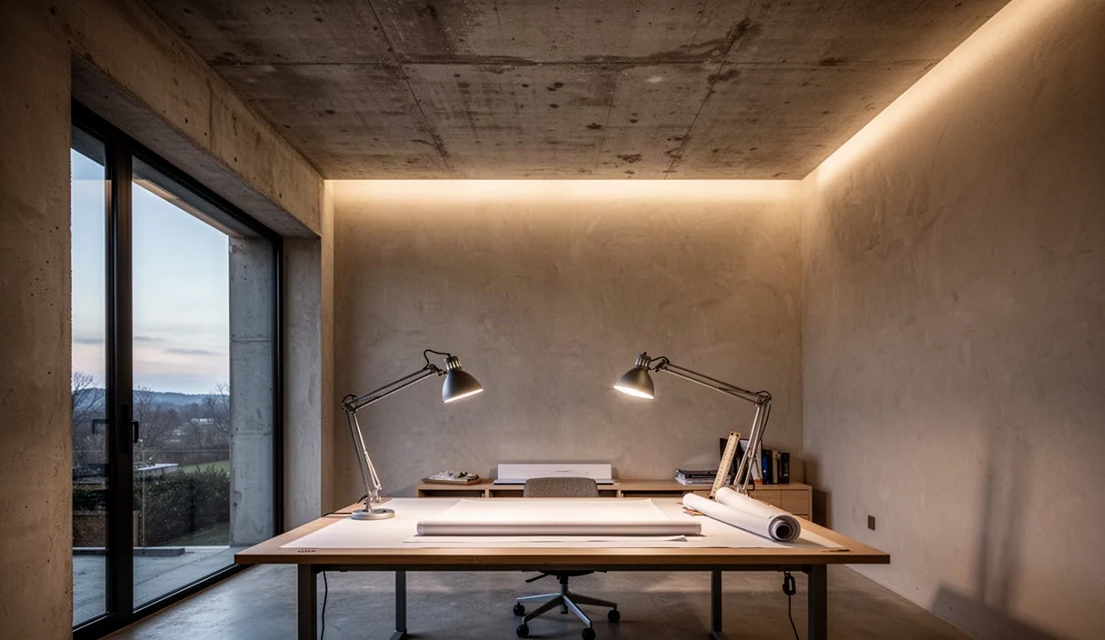

In the design of a professional studio, illumination dictates how comfortably and accurately an occupant perceives form, texture, and color over extended working periods. A room illuminated solely by localized task lamps induces visual fatigue through extreme brightness disparities, whereas an environment flooded exclusively with diffuse light flattens surface relief and deadens visual interest. Achieving an appropriate equilibrium between direct light directed onto the horizontal work plane and indirect light washing the room boundaries remains one of the most critical challenges in studio planning.
The solution requires treating the studio volume as an integrated optical system. Direct task illumination provides the requisite optical clarity for drafting, fine fabrication, or digital color grading, while indirect perimeter illumination maintains spatial orientation and softens adaptation demands on the human eye. Balancing these layers demands rigorous attention to luminance ratios, cove geometries, driver performance, and luminaire placement relative to drawing tables and displays.
The Contrast Problem: Work Surfaces versus Room Perimeters
When an individual shifts their gaze from an intensely lit drafting board to a dim perimeter wall, the eye must continually adjust its pupil aperture and neural adaptation level. This mechanism, termed transient adaptation, leads directly to eye strain, headaches, and diminished visual acuity when repeated across several hours. The Illuminating Engineering Society provides clear guidelines regarding maximum allowable luminance ratios to prevent discomfort, yet many studios diverge significantly from these recommendations by relying on excessive downlighting over tables while leaving vertical surfaces in deep shadow.
To preserve visual comfort, the luminance ratio between the task surface and its immediate surround should not exceed 3:1. The ratio between the task surface and remote surfaces, such as back walls or ceiling perimeters, should remain under 10:1. If a drafting table receives an illuminance of 600 lux, the immediate desk perimeter should measure at least 200 lux, and the surrounding walls should receive no less than 60 lux of vertical illuminance. Exceeding a 10:1 ratio forces the ocular muscles to contract and dilate continuously as the worker glances up from drawings or monitors.
| Relationship | Maximum Recommended Luminance Ratio | Example Task Value | Minimum Perimeter Target |
|---|---|---|---|
| Task to immediate working surround | 3:1 | 600 lux | 200 lux |
| Task to remote vertical boundaries | 10:1 | 600 lux | 60 lux |
| Task to high-angle direct source | 1:10 | 600 lux | Under 6000 cd/m² |
| Display screen to backing wall | 1:3 | 140 cd/m² | 47 cd/m² |
Achieving these targets requires measuring vertical illuminance rather than solely relying on horizontal readings taken at the floor or table surface. A studio may demonstrate an acceptable average horizontal value across the floor plate, yet feel oppressive and cavernous if the walls lack sufficient vertical wash. Incorporating perimeter reflectance reduces this discrepancy, allowing the room envelope to serve as a secondary reflector that mitigates harsh contrasts.
Designing Indirect Cove Runs for Diffuse Reflection
Indirect perimeter coves provide an effective method for introducing diffuse ambient light into a studio without introducing visible point sources. When light is projected upward onto a matte ceiling, the architectural plane functions as an expansive luminaire with low surface brightness. However, improper cove construction often generates bright light streaks, thermal failures, or hard cutoff lines that disrupt the intended uniform glow.
The physical relationship between the cove lip, the luminaire, and the ceiling governs the distribution of reflected light. The following dimensions and material selections yield the most predictable diffuse field:
- Suspension and Stand-off Distance: The light center of the fixture should sit between 250 millimeters and 400 millimeters below the finished ceiling surface. A distance under 200 millimeters concentrates energy into a distinct hot spot directly above the cove, whereas a drop exceeding 450 millimeters may expose the fixture directly to normal standing sightlines.
- Cove Lip Height: The front lip of the cove must rise approximately 25 millimeters above the highest point of the luminaire lens. This prevents direct view of the source from anywhere in the studio while preserving an open angle for light to wash outward across the ceiling.
- Optic Selection: Specify linear LED modules fitted with asymmetric, batwing distributions rather than bare lambertian diffusers. An asymmetric optic throws light across the ceiling toward the center of the room, preventing the illumination from pooling against the adjacent wall.
- Substrate Reflectance: The ceiling finish must be a truly flat, non-specular white paint with a Light Reflectance Value between 82 and 88. Semi-gloss, satin, or eggshell finishes introduce specular reflections that telegraph every imperfection in the drywall work and cause secondary glare.
Linear runs within coves must also be laid with contiguous boards or overlapping flexible strips to eliminate dark gaps at segment joints. When fixtures are butted end-to-end without dedicated through-wiring connections, dark intervals of 15 to 30 millimeters will appear directly on the ceiling, breaking the architectural continuity of the plane.
Selecting Color Rendering Index Metrics for Material Work
Studios dedicated to architecture, textile design, illustration, or industrial prototyping demand lighting that faithfully reveals subtle chromatic differences. Historically, designers relied solely on the General Color Rendering Index, or Ra. This metric calculates fidelity based on eight pastel test colors, entirely omitting saturated hues. A light source can achieve a seemingly high rating of 84 Ra while remaining deficient in its rendition of saturated reds, deep blues, and natural skin tones.
For rigorous studio evaluation, professionals should reference both the extended R9 value and the ANSI/IES TM-30-18 standard. The R9 metric measures saturated red rendering, which is essential for accurate assessment of timber finishes, warm stone, leather, and printing inks. TM-30-18 expands this evaluation to ninety-nine real-world color samples, providing two primary metrics: the Fidelity Index, or Rf, and the Gamut Index, or Rg. The Fidelity Index evaluates accuracy relative to a reference illuminant, while the Gamut Index tracks whether colors appear oversaturated or desaturated under the source.
| Metric | Minimum Studio Requirement | Preferred Studio Baseline | Functional Significance |
|---|---|---|---|
| General CRI (Ra) | 90 | 95 | Broad overall color fidelity across pastel tones |
| Special Index R9 | 65 | 85 | Discrimination of red tones, woods, and warm dyes |
| TM-30 Fidelity (Rf) | 88 | 93 | Fidelity measured across ninety-nine individual swatches |
| TM-30 Gamut (Rg) | 97 | 101 | Maintains natural saturation without chromatic distortion |
When selecting linear LED engines for coves and direct task pendants, ensure that the spectral power distribution contains a continuous curve rather than sharp, isolated peaks in the blue spectrum. Blue-pump LEDs fitted with inferior phosphors often degrade color discrimination between subtle earth tones, dark grays, and navy textiles. When working with critical physical palettes, a certified color specialist or lighting engineer should be consulted to verify spectral reports prior to procurement.
Dimming Curves and Day-to-Night Transitions
Studio work frequently spans early morning daylight, direct afternoon sun, and late night drafting sessions. A lighting system that remains static throughout this span forces the user to struggle against changing adaptation levels. The implementation of digital dimming protocols, such as DALI-2 or dedicated zero-to-ten-volt architectures, provides necessary control, provided the dimming curves match human ocular perception.
The human eye perceives light non-linearly. Measured light values do not correlate to perceived brightness: an electrical dimming setting of 10 percent of rated power results in approximately 32 percent perceived light. If a lighting system employs a linear dimming curve, the occupant will perceive little change throughout the upper half of the control range, followed by an abrupt, uncontrollable drop at the lowest settings. Studios require a logarithmic dimming curve mapped inside the driver software, which scales the power output to match human perceptual sensitivity smoothly down to 1 percent or 0.1 percent.
Balancing Correlated Color Temperature Across Daily Cycles
Tunable white fixtures offer notable utility in studios, allowing Correlated Color Temperature to shift alongside natural exterior daylight. However, such systems must be managed with restraint rather than extreme theatrical variations. The following operational approach preserves visual stability:
- Establish a midday working baseline between 3500 Kelvin and 4000 Kelvin. This neutral spectrum complements diffused northern daylight without introducing an uncomfortably cold cast.
- As exterior light recedes in the late afternoon, reduce overall indirect ceiling wash by approximately 30 percent while maintaining task levels on drawing boards.
- Transition the ambient cove lighting smoothly to 3000 Kelvin or 2700 Kelvin for late-night work, ensuring that driver output drops gradually without flickering or stepped jumps.
- Maintain direct task lights at a constant spectral temperature during material review to ensure that visual judgments remain consistent between viewing sessions.
Positioning Luminaires Relative to Drawing Tables and Screens
Even fixtures with superior color rendering and smooth dimming will cause discomfort if placed carelessly relative to the worker. Direct task illumination must be located to prevent two distinct optical phenomena: veiling reflections, which wash out details on glossy papers or screens, and cast shadows created by the worker's own hands, head, or drafting tools.
For drawing boards and physical fabrication benches, linear task fixtures must never be mounted directly overhead or slightly behind the drafter's head. Such a position casts the worker's silhouette across the drafting sheet. Instead, direct luminaires should be positioned ahead of the table, angled backward between 20 and 30 degrees from the vertical, or brought in from the side opposite the dominant hand. For a right-handed worker, task light entering predominantly from the left side eliminates hand-shadow interference along parallel bars and triangles.
Digital displays require a distinct geometric approach. A computer monitor functions as a semi-specular surface that reflects bright objects located in front of it. Suspended direct-indirect pendants must be hung parallel to the line of sight rather than perpendicular to it, minimizing the reflection of the housing in the screen glass. Furthermore, direct downlight components must feature cut-off shielding angles of at least 30 degrees or micro-prismatic diffusers that keep Unified Glare Rating values below 16.
Where drawing tables and computer screens share the same desk surface, choose articulated arm luminaires equipped with deep-set asymmetric reflectors. This allows the occupant to redirect task illumination onto physical documents at an acute angle, completely shielding the computer monitor from direct beam wash.
Common Mistakes in Studio Lighting
A frequent error involves installing arrays of narrow-beam downlights directly over the center of the room. This configuration creates pronounced scalloping on walls, deep shadows under shelving, and harsh downward shadows beneath the brow of anyone working at a desk, while leaving the ceiling cavity completely dark.
Another prevalent flaw is mixing LED drivers of varying protocols and manufacturers on a single control channel. Combining forward-phase wall dimmers with electronic low-voltage or zero-to-ten-volt drivers results in differential low-end cutoffs, noticeable audible buzzing, and stroboscopic flicker, which causes rapid neurological fatigue during concentrated drafting work.
Finally, studio planners often overlook wall finishes when balancing ambient light. Specifying high-gloss joinery or high-sheen architectural paint within direct line of sight will turn an otherwise comfortable indirect wash into an array of blinding secondary reflections. Wall surfaces intended to diffuse indirect light should always carry a dead-flat or matte finish.
Next Steps for Studio Upgrades
Begin an evaluation of your existing space by conducting a basic illumination survey using a handheld, cosine-corrected photometer. Measure the horizontal illuminance directly on the drafting surface, then turn the sensor perpendicular to evaluate vertical illuminance on the rear and side walls at seated eye level, approximately 1.2 meters above finished floor level. Calculate your existing luminance ratios against the 3:1 and 10:1 standards outlined in this guide.
Before commissioning complete runs of millwork or fixtures, construct a physical mockup of your indirect cove detail using a three-meter length of structural timber and the prospective linear LED extrusion. Power the module in place after sunset to verify that the stand-off distance from the ceiling avoids hot spots and delivers an even wash into the room. If structural alterations or mains rewiring are required to establish separate switching zones for direct and indirect layers, retain a qualified electrical contractor and an architectural lighting designer to ensure regulatory compliance and proper driver pairing.