 Merrion Design Review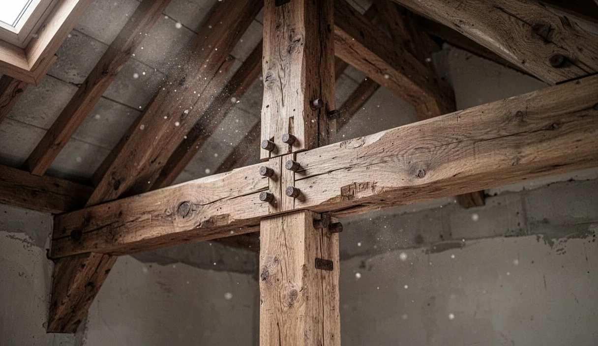

The assessment of historical timber frames requires an appreciation of traditional carpentry alongside rigorous engineering scrutiny. Within surviving post-and-beam assemblies, the health of an entire structure frequently depends upon the integrity of concealed mortise-and-tenon connections, scarf joints, and lap joints. Over centuries, these junction points absorb severe shifts in live load, moisture intrusion, and chemical changes within the wood cell walls. An inspector must therefore approach each frame with systematic methods, observing both the microscopic condition of the grain and the macroscopic alignment of the primary bents.
When conducting these surveys, the objective is never to impose modern tolerances on historic frames, but rather to establish whether movement has stabilized or represents active, catastrophic decline. Joinery that has shifted by a fraction of an inch may have achieved an equilibrium two centuries ago; conversely, a hairline separation accompanied by fresh shearing forces can signal an impending failure. The following guidance outlines the procedural steps and mechanical criteria necessary to execute an exhaustive condition survey on traditional timber joinery.
Preliminary Equipment for Structural Timber Surveys
A timber surveyor cannot rely solely upon visual appraisal from floor level. Accessing the critical joinery of roof trusses, tie beams, and bents demands direct physical access and a specific assortment of diagnostic hand tools. The equipment selected must allow for non-destructive or micro-destructive testing that preserves original material while delivering quantifiable data.
The core kit should contain the following diagnostic items:
- Calibrated Resistance Moisture Meter: An instrument with insulated, deep-wall hammer probes capable of taking moisture readings at depths up to two inches, avoiding superficial surface drying.
- High-Intensity Raking Light: A focused beam of at least five hundred lumens, held nearly parallel to the timber face, to expose surface crushing, hairline grain lifting, and micro-fissures around mortise cheeks.
- Precision Steel Vernier Calipers and Feeler Gauges: For recording exact gaps between shoulders and measuring the diameter and elongation of wooden pins.
- Rigid Stainless Steel Probe or Awl: A blunt-tipped probe used with light hand pressure to locate sub-surface voids without puncturing sound timber fibers.
- Optical Level or Precision Laser Level: Capable of mapping datum planes across multiple bays to measure localized settlements against cumulative building movement.
- Articulated Inspection Borescope: With a flexible shaft under eight millimeters in diameter, useful for looking through existing peg holes or opened joint gaps into the mortise pocket.
Before recording measurements, an inspector must map the ambient environment. Relative humidity and ambient temperature dictate the seasonal equilibrium moisture content of the wood. In unheated historic structures, a timber core moisture reading between twelve and sixteen percent is normal. Readings sustained above eighteen percent demand immediate notation, as the danger threshold for fungal germination begins at twenty percent.
Inspecting Tenon Pins and Joint Tolerances
Traditional joinery depends on wooden pins, often referred to as trunnels or pegs, to draw mortise-and-tenon joints tight during initial assembly. These pins are subjected to high shear stress across the grain. Over extended periods, differential shrinkage between the host post, the entering tenon, and the pin causes mechanical distortion that must be measured with care.
Begin by inspecting the exit and entry faces of each pin. A healthy pin sits flush or slightly proud of the timber face and retains its octagonal or cylindrical cross-section. If a pin appears oval, the surveyor must determine whether the distortion is due to radial shrinkage of the pin itself or transverse shearing caused by tension along the joint. Where a joint has experienced severe pull-out force, the pin will often exhibit stepped fracture marks along the shear planes, visible at the junction between the tenon cheek and the mortise wall.
| Observed Condition | Mechanical Cause | Structural Implication |
|---|---|---|
| Shoulder separation under 0.125 inches | Natural seasonal cross-grain shrinkage | Acceptable; monitor without intervention. |
| Shoulder separation exceeding 0.375 inches | Tension failure or tenon withdrawal | Active concern; peg shear failure likely. |
| Longitudinal splitting at mortise cheek | Eccentric loading or bursting pin pressure | High risk; mortise side wall compromised. |
| Pin sheared flush with mortise interface | Catastrophic lateral or downward shear | Critical; complete loss of mechanical connection. |
Next, examine the joint shoulders. The shoulder of a tenon should bear squarely against the housing of the receiving member to transfer compressive loads. Insert feeler gauges around the perimeter of the joint shoulder. Record any gap variations across the top, sides, and underside. Uneven gap distribution indicates eccentric rotation, suggesting that the beam is twisting along its longitudinal axis or that the vertical post is leaning outward at the top plate.
Diagnosing Differential Deflection Along Beams
Horizontal members such as tie beams, bridging joists, and summer beams sag naturally under self-weight and superimposed floor loads. This natural bending must be separated from problematic differential deflection. Historic timbers often exhibit viscoelastic creep, an irreversible deformation that accumulates over decades under sustained loads without necessarily indicating imminent collapse.
To diagnose the deflection accurately, establish a reference datum:
- Affix a braided nylon string line or direct a self-leveling rotary laser along the tension face of the beam, anchored strictly at the true bearing points over the posts or masonry walls.
- Measure the vertical drop from the reference line to the bottom face of the timber at intervals of one-quarter, one-half, and three-quarters of the clear span.
- Record the depth and width of the timber at mid-span to calculate the existing span-to-depth ratio. A ratio exceeding twenty to one usually exhibits visible sag even under moderate loads.
- Check the top compression face for signs of lateral torsional buckling, where the top of the beam sweeps horizontally out of plumb while sagging vertically.
Differential deflection becomes hazardous when it imposes unintended loads upon neighboring joinery. For example, if a summer beam deflects past one-two-hundred-and-fortieth of its span, the tenons of the floor joists framed into its sides will tilt. The top of the tenon will bear against the mortise roof, while the bottom shoulder pulls away from the mortise face. Look closely for crushing of the wood fibers along the upper edge of the tenon entry hole, which confirms that the deflection has converted a simple horizontal connection into an unintended lever arm.
Differentiating Between Inactive Marks and Active Decay
Historic timbers bear the accumulated marks of their past environments. Distinguishing between damage that ceased a century ago and an ongoing biological threat is a fundamental responsibility of the surveyor. Inappropriate chemical treatments or premature timber removals are often prompted by misinterpreting inactive historical damage as an active infestation.
When inspecting exit holes caused by wood-boring insects, such as the deathwatch beetle or common furniture beetle, look at the color and texture within the flight holes. Freshly cut, pale wood edges and light-colored frass, which is the powdery waste ejected by exiting beetles, demonstrate active infestation within the previous twelve to twenty-four months. Conversely, exit holes whose inner rims are darkened by atmospheric oxidation, accumulated soot, or historic paint coats are inactive. Collect a frass sample on a clean sheet of dark paper: sharp, gritty pellets indicate an old infestation that has dried out, whereas soft, clumped frass often indicates sufficient core moisture to support active larval tunneling.
Fungal decay requires an equally discerning eye. Soft rot and brown rot produce distinctive cubical cracking across the grain, accompanied by severe loss of cross-sectional strength. White rot leaves the wood fibrous, spongy, and bleached. When an area of suspected fungal decay is located, drive an insulated moisture probe into the center of the affected zone and into the surrounding sound wood. If the core moisture content sits below fourteen percent, the fungal organism is dormant and cannot spread, as decay fungi require sustained moisture levels above twenty percent to metabolize cellulose and lignin.
Formulating Repair Schedules Before Intervention
Once data collection is complete, the surveyor must translate raw measurements into an orderly schedule of repairs. The prevailing philosophy of historic conservation requires that existing historic fabric be retained wherever structurally feasible. Total replacement of a compromised timber is considered a failure of technical ingenuity; localized repair, scarfed timber replacements, and discreet internal reinforcement should always take precedence.
A sound repair schedule groups structural deficits into distinct tiers of urgency:
- Tier One: Immediate Stabilization: Apply temporary shores, screw jacks, or dead shores beneath beams displaying active failure, severe shear cracking at tenons, or rot affecting more than forty percent of the cross-section at a bearing point.
- Tier Two: Water Elimination and Environmental Control: Repair flashing defects, roof valleys, or broken masonry joints that feed moisture into the timber heads. Without eliminating the water source, any joinery intervention will fail prematurely.
- Tier Three: Mechanical Joinery Repairs: Formulate specific carpentry repairs, such as piecing in new seasoned oak or softwoods matched in grain orientation, density, and moisture content to the original substrate. Traditional scarf joints secured with dry wooden pegs are preferred over welded steel plates wherever fire regulations and load paths allow.
- Tier Four: Ongoing Monitoring: Install permanent telltales, such as calibrated acrylic movement plates, across stressed joints displaying uncertain movement patterns, scheduling reinspection every six to twelve months.
Every proposed intervention must be documented with measured elevation drawings of the joint, showing the exact cut-lines for Dutchman repairs or timber grafts. These specifications protect the owner and contractor from executing excessive timber removal during the work.
Common Mistakes
The most frequent error in joinery inspection is relying upon outward visual appearances while ignoring internal hidden failures. A beam may appear robust across its central span, yet possess entirely rotten tenons within the cool, damp microclimate of an exterior stone wall pocket. Neglecting to probe bearing ends leaves the most dangerous failure modes unaddressed.
Another persistent mistake involves treating structural movement with rigid, inflexible materials. Packing an expanded mortise with modern epoxy resins or driving steel lag bolts through traditional joints frequently accelerates damage. Historic timber structures must flex in response to wind and temperature changes. Introducing non-yielding materials creates localized stress points, eventually splitting the surrounding historic grain when natural movement resumes.
Practical Next Steps
Upon concluding the survey, compile all field notes, caliper measurements, and moisture profiles into an indexed condition register. Each bent and joinery node should be assigned a systematic alphanumeric tag corresponding to a master framing plan. This nomenclature ensures that carpentry teams, conservation officers, and engineers refer to the precise timber in question.
Where structural anomalies remain ambiguous or indicate progressive deflection, engage an accredited conservation engineer to calculate remaining shear capacities. Long-term monitoring protocols should be established immediately, prioritizing joints that exhibit unresolved shoulder gaps or elevated moisture contents. By maintaining this methodical record, the property custodians secure an empirical basis for all future preservation decisions, ensuring the structural frame endures for generations to come.